The plan
Absolutely no doubt in my mind that this model must be displayed ‘in-flight’ to maintain those sleek and iconic lines.

With this decision made we can forget about some of the inaccuracies and detail issues, example being with the location of the nose wheel bay and the complexity of the drooping nose, along with detailing the undercarriage and main wheel bays, which lack any detail at all in truth. If you choose to have your model sitting on the ground there are photo-etch options out there if you can find them, they seem to be becoming rarer than the kit itself.
So pretty much an OOB build, let’s see if this kit lives up to its beastly reputation, but first a little inspiration.
Concorde, A Supersonic Story is a BBC documentary from 2017.
https://www.youtube.com/watch?v=jnh3PdNN6ps
Let’s get started
The instructions would have you begin with the engine nacelles, but the first order of business is in my opinion, some extensive dry-fitting of the main fuselage parts, to better understand why this kit has the unenviable reputation of a ‘filler eater’…
Certainly a common problem throughout is the lack of contact area for glue at the main fuselage and wing joints, so we will strengthen them all in turn as we go along.
Researching other builds and the problems they faced, it seems one main issue is in part due to the shear length of plastic in the central fuselage section, which despite some internal stiffeners is prone to warping. This is further exacerbated by differing thickness of plastic on the main fuselage and tail section, it’s here that the root of the infamous ‘step’ at the tail seam joint resides.
The instructions would have you make up the fuselage and tail halves before joining them, leaving you with that step to deal with, I decided to forego that method and join one side of the central fuselage to the respective tail part first.
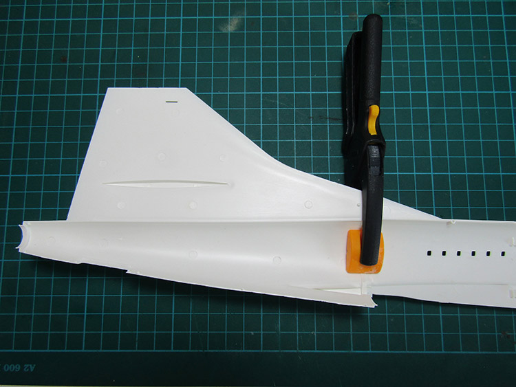
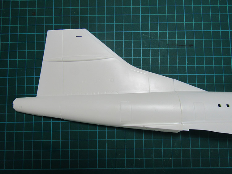
In this way I hope to reduce the step to a more acceptably flush joint and also be able to strengthen it on the inside.
After tacking the join lightly with cyano, we can build up the strength with some spacers and straps.
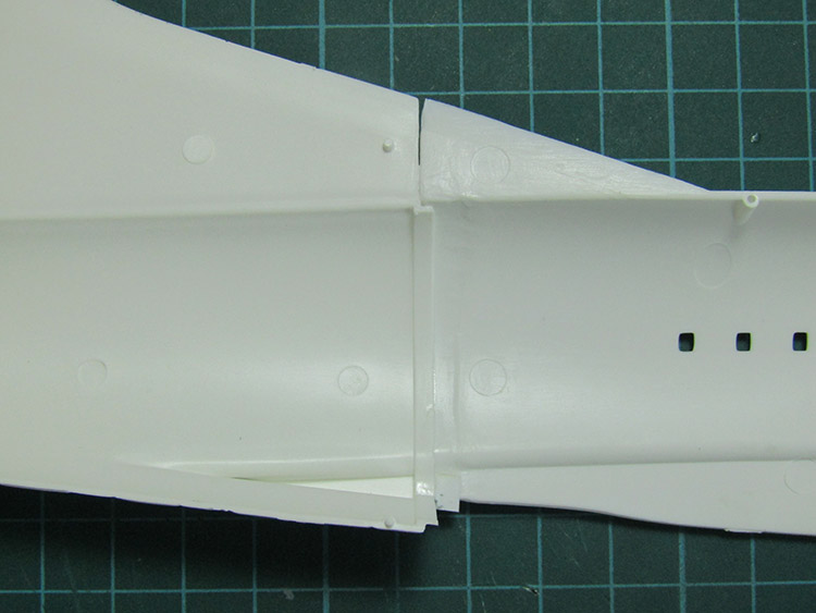
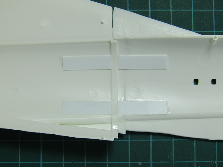
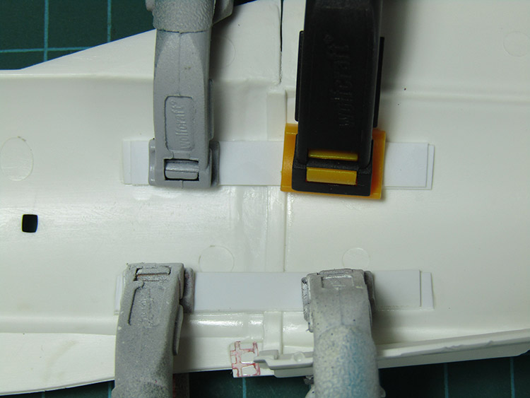
Each side of the joint flange needs a styrene strip spacer, followed by straps over the top. Repeat for the other half and then for additional security I applied some two part epoxy across the lot.
After a coat of primer and light grey inside, the completed halves can have the stiffener bulkheads fitted and be joined along the seams in the normal manner.
Paul Ainsworth says
“Hello,Mick” – That’s an epic build of a very-challenging kit but your results speak for themselves in those photos.
I’ve seen this kit (unmade) and saw how daunting a prospect it is to build.
You’ve made a fantastic job of it and she’s a magnificent tribute to the legendary ‘Concorde’. Superb modelling.🏆
Best Regards,
Paul.😉👍